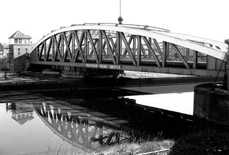
Trafford Road Swing Bridge
Carried out under the supervision of Sir Edward Leader Williams and built by the John Butler Iron Works of Stanningley, near Leeds in 1892, Trafford Road Swing Bridge was the last of seven swing-bridges that once spanned the Manchester Ship Canal. Allowing access for ocean going vessels to Pomona Dock (1-4 dock) and the wharves on the Salford bank, it was the largest, heaviest and widest of the ship canal's swing bridges,
TRAFFORD ROAD SWING BRIDGE - Main Span 129 ft. 6 in. Rear Span 82 ft. 3 in. Total Length over all 211 ft. 9 in. Height of Girders 30 ft. Width of Roadway 46 feet; Cart way 36 ft. Diameter of Roller Path (centres) 9 ft. 6 in. Number of Rollers 64. Weight when swinging 1,800 tons. Constructed by Messrs. John Butler & Co., of Stanningley. The bridge is worked by two hydraulic engines with independent gear, each being of sufficient power to open or close the bridge under ordinary conditions, but so arranged that they can be worked in conjunction if required. They are of Sir W. G. Armstrong, Mitchell & Co.'s ordinary type, with oscillating cylinders fitted with gun-metal plungers, gun-metal working and reversing valves, and oscillating joints. The bridge is turned by a cast steel rack fitted to the annular girder above the upper roller path. A central hydraulic ram 4 ft. 10 in. in diameter is provided, fitted with plunger and fixed to a cast iron bearing plate under the transverse girders of the bridge. During the operation of swinging one half of the weight of the bridge is taken by the central ram, reducing the load upon the rollers to 900 tons. The weight on the rollers is thus brought down to the initial load of 800 lbs. per lineal inch, the standard adopted for the whole of the rollers of the Swing Bridges throughout the Canal. Hydraulic gear for lifting and blocking the ends of the bridge, together with a locking bolt and disengaging gear are also provided. The movements of the bridge are arranged so as to be under the control of one valve man in the central cabin. [Transactions for 1896. Manchester Association of Engineers, Manchester 1897:161]